
Page 34 - DCAP206_INTRODUCTION_TO_COMPUTER_ORGANIZATION_AND_ARCHITECTURE_DCAP502_COMPUTER_ORGANIZATION_AND_ARCHITECTURE
P. 34
Unit 2: Devices Used in Digital Electronics
Notes
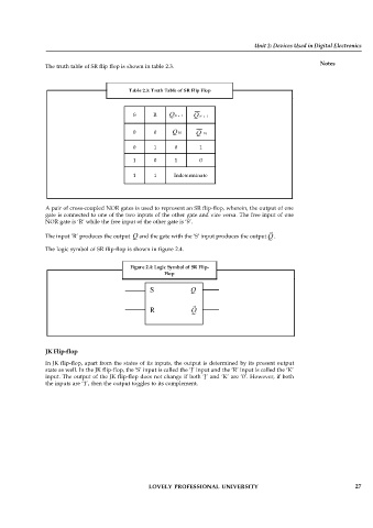
The truth table of SR flip flop is shown in table 2.3.
Table 2.3: Truth Table of SR Flip Flop
S R Q N 1 Q N 1
0 0 Q N Q N
0 1 0 1
1 0 1 0
1 1 Indeterminate
A pair of cross-coupled NOR gates is used to represent an SR flip-flop, wherein, the output of one
gate is connected to one of the two inputs of the other gate and vice versa. The free input of one
NOR gate is ‘R’ while the free input of the other gate is ‘S’.
The input ‘R’ produces the output Q and the gate with the ‘S’ input produces the output Q .
The logic symbol of SR flip-flop is shown in figure 2.4.
Figure 2.4: Logic Symbol of SR Flip-
Flop
S Q
R Q
JK Flip-flop
In JK flip-flop, apart from the states of its inputs, the output is determined by its present output
state as well. In the JK flip-flop, the ‘S’ input is called the ‘J’ input and the ‘R’ input is called the ‘K’
input. The output of the JK flip-flop does not change if both ‘J’ and ‘K’ are ‘0’. However, if both
the inputs are ‘1’, then the output toggles to its complement.
LOVELY PROFESSIONAL UNIVERSITY 27