
Page 61 - DCAP206_INTRODUCTION_TO_COMPUTER_ORGANIZATION_AND_ARCHITECTURE_DCAP502_COMPUTER_ORGANIZATION_AND_ARCHITECTURE
P. 61
Computer Organization and Architecture/Introduction to Computer Organization and Architecture
Notes
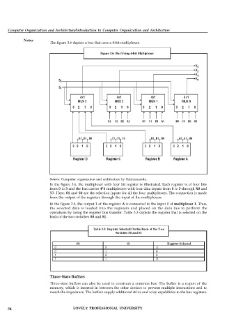
The figure 3.6 depicts a bus that uses a 4-bit multiplexer.
Figure 3.6: Bus Using 4-bit Multiplexer
Source: Computer organization and architecture by Krishnananda.
In the figure 3.6, the multiplexer with four bit register is illustrated. Each register is of four bits
from 0 to 3 and the bus carries 4*1 multiplexers with four data inputs from 0 to 3 through X0 and
X3. Here, S1 and S0 are the selection inputs for all the four multiplexers. The connection is made
from the output of the registers through the input of the multiplexers.
In the figure 3.6, the output 1 of the register A is connected to the input 0 of multiplexer 1. Thus,
the selected data is loaded into the registers and placed on the data bus to perform the
operations by using the register bus transfer. Table 3.3 depicts the register that is selected on the
basis of the two switches S0 and S1.
Table 3.3: Register Selected On the Basis of the Two
Switches S0 and S1
S0 S1 Register Selected
0 0 A
0 1 B
1 0 C
1 1 D
Three-State Buffers
Three-state buffers can also be used to construct a common bus. The buffer is a region of the
memory, which is inserted in between the other devices to prevent multiple interactions and to
match the impedance. The buffers supply additional drive and relay capabilities to the bus registers.
54 LOVELY PROFESSIONAL UNIVERSITY