
Page 11 - DCAP507_SYSTEM_SOFTWARE
P. 11
Unit 1: Introduction to System Software
Notes
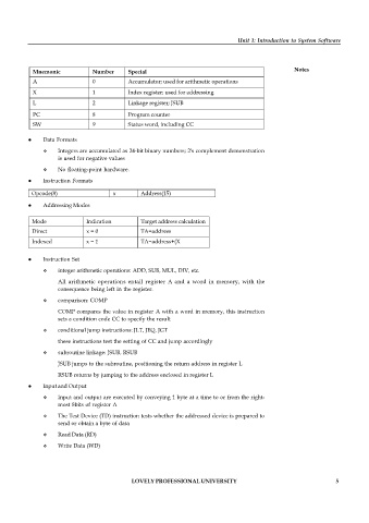
Mnemonic Number Special
A 0 Accumulator; used for arithmetic operations
X 1 Index register; used for addressing
L 2 Linkage register; JSUB
PC 8 Program counter
SW 9 Status word, including CC
Data Formats
Integers are accumulated as 24-bit binary numbers; 2's complement demonstration
is used for negative values
No floating-point hardware.
Instruction Formats
Opcode(8) x Address(15)
Addressing Modes
Mode Indication Target address calculation
Direct x = 0 TA=address
Indexed x = 1 TA=address+(X
Instruction Set
integer arithmetic operations: ADD, SUB, MUL, DIV, etc.
All arithmetic operations entail register A and a word in memory, with the
consequence being left in the register.
comparison: COMP
COMP compares the value in register A with a word in memory, this instruction
sets a condition code CC to specify the result
conditional jump instructions: JLT, JEQ, JGT
these instructions test the setting of CC and jump accordingly
subroutine linkage: JSUB, RSUB
JSUB jumps to the subroutine, positioning the return address in register L
RSUB returns by jumping to the address enclosed in register L
Input and Output
Input and output are executed by conveying 1 byte at a time to or from the right-
most 8bits of register A
The Test Device (TD) instruction tests whether the addressed device is prepared to
send or obtain a byte of data
Read Data (RD)
Write Data (WD)
LOVELY PROFESSIONAL UNIVERSITY 5